1. Why Can Power Cables Interfere with Signal Cables?
Power cables and signal cables perform different jobs.
Power cables deliver electrical energy to motors, drives, heaters, and other equipment. Signal cables carry information between sensors, encoders, controllers, and communication devices.
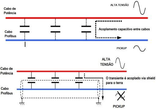
When electrical current flows through a conductor, it produces a magnetic field. When voltage changes, it can also create an electric field. Under certain conditions, these fields can couple into nearby cables and introduce unwanted electrical noise.
This is known as electromagnetic interference, or EMI.
The risk depends on several factors:
-
The current and voltage involved.
-
How quickly the electrical signals change.
-
The distance between the cables.
-
How long the cables run alongside each other.
-
The cable construction and shielding.
-
The grounding and bonding arrangements.
-
The sensitivity of the signal circuit.
For example, a motor cable connected to a variable frequency drive (VFD) may carry rapidly switching electrical waveforms. If a sensitive encoder or analog signal cable runs alongside it for a long distance, interference may become more likely.
However, proximity alone does not guarantee a problem. A properly designed installation may work reliably even when different cable types share a route.
The goal is not simply to separate every cable. It is to control interference according to the electrical environment and the sensitivity of the signal.
2. What Problems Can Occur When Cables Are Too Close?
Problem 1: Unstable Sensor Signals
Sensors often transmit relatively low-level signals to a PLC or other control system.
If electrical noise couples into a sensor cable, the receiving device may interpret the interference as part of the intended signal.
Possible symptoms include:
-
Unexpected sensor switching.
-
Fluctuating analog readings.
-
False alarms.
-
Inconsistent measurements.
-
Intermittent control responses.
For example, a proximity sensor may occasionally appear to detect an object when nothing is present. Before replacing the sensor, engineers should check the wiring route, shielding, grounding, and nearby electrical noise sources.
Of course, a faulty sensor, loose connection, or incorrect configuration can produce similar symptoms. Cable routing is one possible cause—not automatically the answer.
Problem 2: Encoder Errors and Positioning Inaccuracy
Encoders provide feedback about position, speed, or movement.
In automated machinery, this information helps controllers coordinate motors, conveyors, robotic arms, and positioning systems.
If interference affects the encoder signal, the system may experience communication errors, invalid readings, or unexpected motion-related faults.
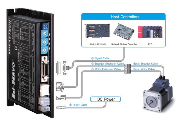
The consequences depend on the encoder interface and the control system. Some systems detect corrupted data and report an error, while others may show unstable readings or degraded performance.
The risk deserves particular attention when encoder cables run near motor power cables, especially those connected to switching drives.
In these applications, engineers should consider cable separation, suitable shielded cable, correct termination, and the manufacturer's installation requirements.
Problem 3: Communication Errors
Industrial communication cables can also be affected by an electrically noisy environment.
Depending on the interface and installation, interference may contribute to:
-
Increased communication errors.
-
Intermittent data loss.
-
Network instability.
-
Unexplained equipment alarms.
-
Difficult troubleshooting.
Not every communication failure is caused by electromagnetic interference. Incorrect termination, damaged connectors, excessive cable length, poor installation, and incompatible components can create similar symptoms.
Still, if communication problems occur mainly when motors or drives start operating, the cable routing deserves attention.
Problem 4: Unexpected Machine Stops
This is where a seemingly small wiring decision can become an expensive production issue.
Imagine an automated packaging line. A motor drive starts, a nearby signal becomes unstable, and the controller detects an unexpected condition. The machine stops while an operator investigates.
If the issue occurs repeatedly, the maintenance team may replace sensors, inspect PLC programs, and test communication devices without finding a clear fault.
The actual cause could be a combination of electrical noise, unsuitable cable construction, grounding problems, or routing practices.
Unnecessary downtime can cost far more than the additional time required to plan cable routing correctly.
That is why cable selection and installation should be considered during machine design—not only after a fault appears.
3. Which Cable Combinations Deserve Extra Attention?
Not all power and signal cables present the same level of interference risk.
The following combinations deserve particular attention during industrial installation.
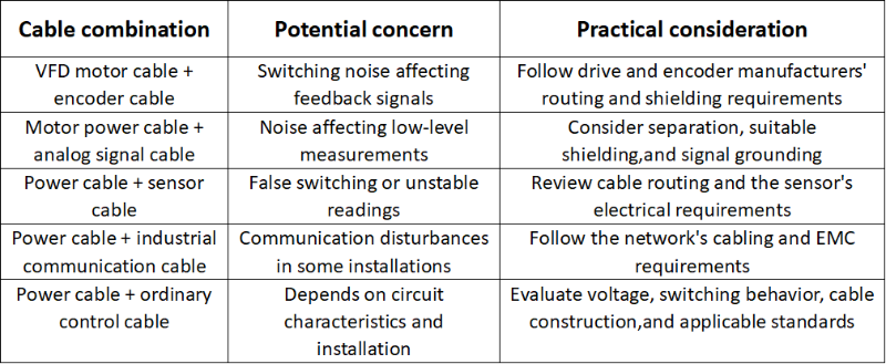
The important point is that cable function alone does not determine compatibility.
A shielded signal cable may perform well in a demanding environment when installed correctly. An unshielded cable may also work reliably in a suitably controlled installation.
The appropriate solution depends on the actual electrical conditions, cable specifications, and equipment requirements.
4. How Should Power and Signal Cables Be Routed?
There is no single separation distance that applies to every industrial installation.
Required separation may depend on the applicable standard, cable category, installation environment, drive manufacturer's instructions, and the characteristics of the signal circuit.
Nevertheless, several good practices can reduce the risk of interference.
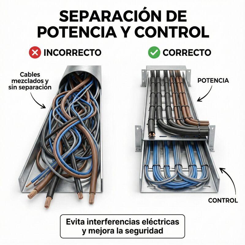
1. Separate Power and Sensitive Signal Cables Where Practical
Where possible, route motor power cables and sensitive signal cables through separate cable trays, ducts, or compartments.
This can reduce electromagnetic coupling and make the installation easier to inspect and maintain.
For parallel cable runs, greater separation generally reduces coupling, although the actual benefit depends on the cable construction and electrical environment.
Do not apply a universal distance without checking the requirements of the specific installation.
2. Minimize Long Parallel Runs
When power and signal cables must occupy the same general area, avoid running them alongside each other for unnecessary distances.
Longer parallel runs can increase the opportunity for interference to couple from one cable into another.
Where practical, route the cables separately and cross them at approximately 90 degrees when they must intersect.
Right-angle crossing is a useful installation practice, but it does not eliminate all interference. The effectiveness also depends on the electrical environment and cable design.
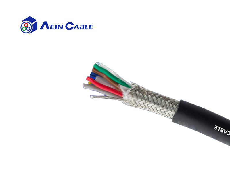
3. Choose Appropriate Shielded Cables
Shielding can help reduce electromagnetic coupling, but not all shielding arrangements provide the same performance.
Depending on the application, options may include foil shielding, braided shielding, or combined shielding structures.
The choice should consider:
-
The type and frequency of interference.
-
The signal interface.
-
Cable flexibility requirements.
-
Mechanical stress and movement.
-
Environmental conditions.
-
Shield termination and bonding requirements.
For example, a signal cable used in a moving automation system must be suitable not only for electromagnetic performance but also for repeated flexing.
A cable that performs well in a fixed installation may not be appropriate for continuous movement inside a drag chain.
4. Pay Attention to Grounding and Shield Termination
A shield cannot deliver its intended performance if the installation ignores the manufacturer's grounding and bonding instructions.
Poor shield termination, inappropriate bonding arrangements, and long connection leads can reduce shielding effectiveness or introduce other EMC problems.
The correct approach depends on the signal interface, frequency range, equipment design, and applicable EMC requirements.
For drive systems, follow the drive manufacturer's instructions for motor cable shielding, protective earth, and bonding. Do not assume that every cable shield should be connected in exactly the same way.
5. Select Cables for the Actual Application
Cable selection should consider more than rated voltage and conductor size.
For industrial automation, engineers may also need to evaluate:
-
Electromagnetic compatibility.
-
Shielding construction.
-
Capacitance and electrical characteristics.
-
Continuous-flex performance.
-
Oil and abrasion resistance.
-
Temperature range.
-
Minimum bending radius.
-
Applicable electrical and installation standards.
A cable intended for fixed installation may not withstand repeated movement. A cable designed for continuous flexing may still be unsuitable for a particular signal interface if its electrical characteristics do not meet the system requirements.
The best cable is the one that satisfies the electrical, mechanical, and environmental requirements of the application.
5. How Can You Tell Whether Cable Routing Is the Real Problem?
If a machine experiences intermittent faults, changing the cable immediately may not be the most efficient first step.
A systematic investigation can help identify the cause.
Step 1: Look for a Repeatable Pattern
Does the fault occur when a motor starts, a drive changes speed, or a high-current device switches on?
A repeatable relationship between the fault and the operation of electrical equipment can indicate an interference problem.
It is a useful clue, but not conclusive proof.
Step 2: Inspect the Cable Route
Check whether sensitive signal cables run alongside motor power cables, switching power circuits, or other potential noise sources.
Look for long parallel sections, shared cable compartments, damaged cable jackets, and incorrect routing.
Step 3: Check the Shielding and Connections
Inspect shield termination, grounding, connectors, and bonding arrangements against the equipment manufacturer's requirements.
A shielded cable with poor termination may not provide the expected protection.
Step 4: Review the Electrical Interface
Confirm that the cable matches the signal type and interface requirements.
For example, an analog signal, an encoder interface, and an industrial Ethernet connection may have different cable requirements.
Do not assume that one general-purpose cable is suitable for every signal.
Step 5: Test Changes Methodically
Where it is safe and practical, qualified personnel can test an alternative routing arrangement or temporarily separate the suspected cables to determine whether the fault changes.
Document the results rather than making several wiring changes at once.
For safety, never disconnect protective earth conductors or defeat required shielding and bonding arrangements as a troubleshooting shortcut. Follow appropriate isolation procedures when working on electrical equipment.
6. Cable Routing Is Only One Part of the Solution
It is tempting to blame every intermittent machine fault on electromagnetic interference. In practice, reliable industrial wiring depends on several factors working together.
These include:
-
Correct cable selection.
-
Appropriate routing and separation.
-
Proper grounding and bonding.
-
Suitable connectors and termination.
-
Correct installation and bending practices.
-
Compliance with equipment and system requirements.
A high-quality cable cannot compensate for every installation error. Similarly, excellent routing cannot make an electrically unsuitable cable appropriate for a demanding application.
The best results come from treating cable selection, system design, and installation as parts of the same engineering process.
At AEIN, we believe cable reliability is critical for industrial automation performance. Choosing the right cable means looking beyond the product name to understand how it will operate within the complete system.
For applications involving motor drives, encoders, sensors, robots, and moving machinery, evaluating the electrical and mechanical requirements early can help reduce installation problems and support long-term reliability.
Final Thoughts
What happens when power and signal cables are routed too close together?
In some installations, nothing noticeable happens. In others, electromagnetic interference may contribute to unstable sensor readings, encoder errors, communication problems, or unexpected machine stops.
The difference depends on the electrical environment, cable design, signal sensitivity, and installation quality.
The practical lesson is simple: do not treat cable routing as an afterthought.
Separate power and sensitive signal circuits where appropriate, minimize unnecessary parallel runs, select cables for the real application, and follow the relevant EMC and equipment requirements.
If your machine suffers from intermittent faults that are difficult to reproduce, take a closer look at the wiring route before replacing components without a clear diagnosis.
Sometimes, the problem is not the sensor, the controller, or the software. It may be the way the cables work together inside the machine.
Frequently Asked Questions
Can power cables and signal cables be installed in the same cable tray?
Sometimes, yes. Whether this is acceptable depends on the applicable standards, cable types, voltage levels, installation conditions, and equipment requirements. Separate compartments or separate routes may be necessary in some applications.
Do shielded signal cables eliminate electromagnetic interference?
No. Shielding can reduce interference, but performance depends on the cable construction, installation, shield termination, grounding, and type of interference.
Should power and signal cables always cross at 90 degrees?
Crossing at approximately 90 degrees is a useful way to reduce coupling at intersections. However, it does not eliminate all interference or replace any required cable separation.
Are VFD motor cables a particular concern for encoder cables?
They can be. VFDs generate rapidly switching electrical waveforms that may create challenging EMC conditions. Follow the drive and encoder manufacturers' cable-routing, shielding, and bonding requirements.
How can I choose the right cable for an industrial automation system?
Start with the electrical interface, voltage, current, signal characteristics, installation environment, and movement requirements. Then evaluate shielding, mechanical performance, environmental resistance, and applicable standards.